| Mastr II | |||||||||
| ICOM Integrated Circuit Oscillator Module | |||||||||
| Transmitter | |||||||||
| Comb. No. Freq Range Digits | Freq Band | Formula | Crystal Range (MHz) | Std / PLL | 5ppm 5C ICOMS | 5ppm EC ICOMS | 5ppm FCC Types KT-* | 2ppm 2C ICOMS | 2ppm FCC Types KT- |
| 12 | 25-30 | Fo/3 | 8.33-10 | Std | 19A129393G19 | 19A129393G16 | 1 | 19A129393G13 | 2 |
| 13 | 29.7-36 | Fo/3 | 9.9-12 | Std | 19A129393G19 | 19A129393G16 | 1 | 19A129393G13 | 2 |
| 23 | 36-42 | Fo/3 | 12-14 | Std | 19A129393G19 | 19A129393G16 | 1 | 19A129393G13 | 2 |
| 33 | 42-50 | Fo/3 | 14-16.67 | Std | 19A129393G19 | 19A129393G16 | 1 | 19A129393G13 | 2 |
| 44,45 | 66-88 | Fo/6 | 11-14.67 | Std | 19A129393G40 | 19A129393G39 | 155-A, 156-A, 157-A | 19A129393G38 | 155-A, 156-A, 157-A |
| 56 | 138-155 | Fo/12 | 11.5-12.92 | Std | 19A129393G20 | 19A129393G17 | 3 | 19A129393G14 | 4 |
| PLL | 19A130605G8 | 19A120605G14 | 5 | 19A130605G1 | 5 | ||||
| 66 | 150.8-174 | Fo/12 | 12.56-14.5 | Std | 19A129393G20 | 19A129393G17 | 3 | 19A129393G | 4 |
| PLL | 19A130605G9 | 19A130605G15 | 5 | 19A130605G2 | 6 | ||||
| 77 | 406-420 | Fo/36 | 11.27-11.66 | Std | 19A129393G21 | 19A129393G18 | 7 | 19A129393G15 | 8 |
| PLL | 19A130605G | No FCC Type # | |||||||
| 78 | 420-450 | Fo/36 | 11.66-12.5 | Std | 19A129393G21 | 19A129393G18 | 7 | 19A129393G15 | 8 |
| 88 | 450-470 | Fo/36 | 12.5-13.05 | Std | 19A129393G21 | 19A129393G18 | 7 | 19A129393G15 | 8 |
| PLL | 19A130605G11 | 19A130605G17 | No FCC Type # | 19A130605G4 | 9 | ||||
| 89 | 470-494 | Fo/36 | 13.05-13.72 | Std | 19A129393G21 | 19A129393G18 | 7 | 19A129393G15 | 8 |
| PLL | 19A130605G5 | 9 | |||||||
| 91 | 494-512 | Fo/36 | 13.72-14.222 | Std | 19A129393G21 | 19A129393G18 | 7 | 19A129393G15 | 8 |
| PLL | 19A130605G13 | No FCC Type # | 19A130605G6 | 9 | |||||
| 96 | 851-870 | Fo/48 | 17.729-18.125 | Std | 19A136999G6 (1ppm) | 150-A, 185-A, 189-A | |||
| Receiver | |||||||||
| Comb. No. Freq Range Digits | Freq Band | Formula | Crystal Range (MHz) | 5ppm 5C ICOMS | 5ppm EC ICOMS | 2ppm 2C ICOMS | 2ppm FCC Types | ||
| 12 | 25-30 | (Fo+11.2)/3 | 23.06-13.73 | 19A129393G10 | 19A129393G6 | 19A129393G2 | ER-63-A | ||
| 13 | 29.7-36 | (Fo+9.4)/3 | 13.13-15.13 | 19A129393G9 | 19A129393G5 | 19A129393G1 | ER-63-A | ||
| 23 | 36-42 | (Fo+11.2)/3 | 15.73-17.73 | 19A129393G10 | 19A129393G6 | 19A129393G2 | ER-63-A | ||
| 33 | 42-50 | (Fo+9.4)/3 | 17.13-19.8 | 19A129393G9 | 19A129393G5 | 19A129393G1 | ER-63-A | ||
| 44, 45 | 66-88 | (Fo-11.2)/6 | 12.86-16.54 | 19A129393G37 | 19A129393G36 | 19A129393G35 | ER-101-A | ||
| 56 | 138-155 | (Fo-11.2)/9 | 14.08-15.98 | 19A129393G11 | 19A129393G7 | 19A129393G3 | ER-64-A | ||
| 66 | 150.8-174 | (Fo-11.2)/9 | 15.51-18.08 | 19A129393G11 | 19A129393G7 | 19A129393G3 | ER-64-A | ||
| 138-174 (Note 1) | (Fo+11.2)/9 | 16.57-20.57 | 19A130283G5 | 19A130283G3 | 19A130283G1 | ER-64-A | |||
| 77 | 406-420 | (Fo-11.2)/27 | 14.62-15.14 | 19A129393G12 | 19A129393G8 | 19A129393G4 | ER-65-A | ||
| 78 | 420-450 | (Fo-11.2)/27 | 15.14-16.25 | 19A129393G12 | 19A129393G8 | 19A129393G4 | ER-65-A | ||
| 88 | 450-470 | (Fo-11.2)/27 | 16.25-16.99 | 19A129393G12 | 19A129393G8 | 19A129393G4 | ER-65-A | ||
| 89 | 470-494 | (Fo-11.2)/27 | 16.99-17.88 | 19A129393G12 | 19A129393G8 | 19A129393G4 | ER-65-A | ||
| 91 | 494-512 | (Fo-11.2)/27 | 17.88-18.54 | 19A129393G12 | 19A129393G8 | 19A129393G4 | ER-65-A | ||
| 450-512 (Note 1) | (Fo+11.2)/27 | 17.08-19.38 | 19A130283G6 | 19A130283G4 | 19A130283G2 | ER-65-A | |||
| 92 | 806-820 | (Fo-45)/48 | 15.85-16.25 | 19A136999G7 (1 ppm) | ER-97-D | ||||
| Note 1 | Formula is for high side injection option and is required for E series when combination number 6th digit is A thru P and 7th digit is D or L; and, is not used for Mastr II Stations. HB rcvrs (138-174 MHz) require Option 9054 | ||||||||
| Note 2 | Mastr II Radios may use either 5ppm or 2 ppm ICOM as follows: | ||||||||
| 2a | Use all 2C ICOMs when 10th Digit is B | ||||||||
| 2b | In M series radios, use only one 5C ICOM (Master) (normally in F1 position) and all others must be EC ICOMs (slave) | ||||||||
| 2c | In E Series (system package) mobiles using 5 ppm ICOMs, a 5C ICOM is required in each layer (top and bottom) and all others must be EC ICOMs | ||||||||
| 2d | In all Mastr II Stations using 5 ppm ICOMs, a 5C ICOM is required in the transmitter and one in the receiver. EXCEPTION-only one 5C ICOM is required in the Intermittent Duty, Local Control Station. | ||||||||
| Note 3 | For Mastr II DFE (Dual Front End) receivers with non-matching IF's, a second mixer/converter (19C320691G1) is used to convert the 9.4 MHz IF to 11.2 MHz. Use xtal 19B226002G1 (1.8 MHz) | ||||||||
| PLL: Phase Locked Loop Exciter Models with FM Modulated Oscillator Modules | |||||||||
| STD: Standard Models. | |||||||||
| FCC Type Acceptance List for Transmitters: (The lists shown below contain the FCC Transmitter Type Numbers that may be applicable to the channel elements referencing that particular list. The letters "KT-" are assumed as a prefix for each type number listed. For an example, a listing of "30-A" would represent the FCC Transmitter Type "KT-30-A". | |||||||||
| 1 | 30-A, 31-A, 39-A, 56-A, 58-A, 59-A, 60-A, 61-A, 70-A, 70-E, 71-A, 80-A, 80-E, 81-A. | ||||||||
| 2 | 30-C, 31-C, 39-C, 56-C, 57-C, 58-C, 59-C, 60-C, 61-C, 70-C, 70-G, 71-C, 80-C, 80-G, 81-C | ||||||||
| 3 | 32-B, 33-A, 34-A, 41-B, 42-A, 43-A, 44-B, 45-A, 46-A, 47-B, 48-A, 49-A, 72-B, 72-F, 73-A, 73-E, 74-A, 78-A, 79-A, 82-B, 82-F, 83-A, 83-E, 84-A, 100-B, 204-A | ||||||||
| 4 | 32-C, 33-C, 34-C, 41-B, 42-C, 43-C, 44-B, 45-C, 46-C, 47-B, 48-C, 49-C, 72-B, 72-F, 73-C, 73-G, 74-C, 78-A, 79-A, 82-B, 82-F, 83-C, 83-G, 84-C, 100-B, 204-A. | ||||||||
| 5 | 32-K, 33-J, 34-J, 41-J, 42-J, 43-J, 44-J, 45-J, 46-J, 47-J, 48-J, 49-J, 72-J, 73-J, 73-K, 74-J, 78-J, 79-J, 204-J | ||||||||
| 7 | 35-B, 35-D, 36-B, 37-A, 75-B, 75-F, 76-B, 76-F, 77-A, 85-B, 85-F, 86-B, 86-F, 87-A, 101-B, 102-B, 112-A, 119-A, 126-A | ||||||||
| 8 | 35-C, 35-D, 36-C, 36-D, 37-C, 50-D, 51-D, 52-D, 53-D, 54-D, 55-D, 75-D, 75-H, 76-D, 76-H, 77-C, 85-D, 85-H, 86-D, 86-H, 87-C, 88-C, 101-D, 102-D, 112-C, 113-C, 114-C, 115-C, 1`16-C, 117-C, 118-C, 119-C, 126-C, 200-C | ||||||||
| 9 | 50-K, 51-K, 52-K, 53-K, 54-K, 55-K, 113-K, 114-K, 115-K, 116-K, 117-K, 118-K, 200-K. | ||||||||
| From the GE Parts and Accy Catalog - Page 22.4 and 22.5 Index to Channel Oscillators and Crystals Dated 12/90 | |||||||||

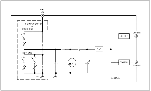
800 MHz Version
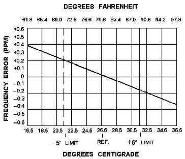
The 2C ICOM is
2 ppm over a range of -40° to +158° F.
The 5C ICOM is
2 ppm from +32° to + 131° degrees F and
5 ppm from - 40° to + 158° F.
The EC (Externally Compensated) ICOM is
2 ppm from + 32° to + 131° F
(with or without compensation *if* a stable compensation voltage of 5 volts is applied) and
5 ppm from - 40° to + 158° F
if compensated by a 5C.
For highest stability, install two 2C ICOM's in the radio, one for receive and one for transmit. The 2C cannot compensate another element, nor is it affected by other ICOM's in the radio. Send the element(s) into the crystal manufacturer for compensation when ordering the particular crystal that is needed for your frequency. This will ensure that the ICOM stays on frequency when the element is in the range where compensation occurs.
The compensation line doesn't exist between the exciter and receiver in a Station, with the exception of the Intermittent duty, local control station. With most base station models, you must make sure both the exciter and receiver are compensated separately.
Here are some excerpts from Mastr II maintenance manuals.
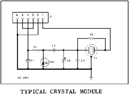
Three different types of ICOMs are available for use in the exciter. Each of the ICOMs contains a crystal-controlled Colpitts oscillator, and two of the ICOMs contain compensator ICs.
The different ICOMs are:
5C-ICOM - contains an oscillator and a 5 part-per-million (±0.0005%) compensator IC, Provides compensation for EC-ICOMs.
EC-ICOM - contains an oscillator only. Requires external compensation from a 5C-ICOM.
2C-ICOM - contains an oscillator and a 2 PPM (±0.0002%) compensator IC. Will not provide compensation for an EC-ICOM.
The ICOMs are enclosed in an RF shielded can with the type ICOM (5C-ICOM, EC-ICOM or 2C-ICOM) printed on the top of the can. Access to the oscillator trimmer is obtained by prying up the plastic tab on the top of the can. The tabs can also be used to pull the ICOMs out of the radio.
Frequency selection is accomplished by switching the ICOM keying lead (terminal 6) to A- by means of the frequency select or switch on the control unit. In single-frequency radios, a jumper from H9 to H10 in the control unit connects terminal 6 of the ICOM to A-. The oscillator is turned on by applying a keyed +10 Volts to the external oscillator load resistor.
In Standard 5 PPM radios using EC-ICOMs, at least one 5C-ICOM must be used. The 5C-ICOM is normally used in the receiver Fl position, but can be used in any transmit or receive position. One 5C-ICOM can provide compensation for up to 15 EC-ICOMs in the transmit and receiver. Should the 5C-ICOM compensator fail in the open mode, the EC-ICOMs will still maintain 2 PPM frequency stability from 0° C to 55° C (+32° F to 131° F) due to the regulated compensation voltage (5Volts) from the 10-Volt regulator IC. If desired, up to 16 5C-ICOMs may be used in the radio.
The 2C-ICOMs are self-compensated at 2 PPM and will not provide compensation for EC-ICOMs.
Rated stability of the 1PPM ICOM is maintained over a temperature range of -30° C to +85° C (-22° F to +185° F). The 1PPM ICOM is used in the 800 MHz radio.
Oscillator Circuit
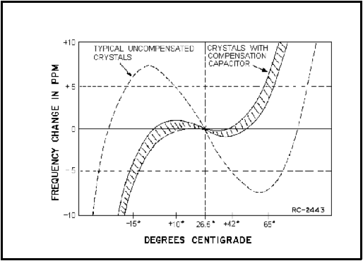
The quartz crystals used in ICOMs exhibit the traditional "S" curve characteristics of output frequency versus operating temperature. At both the coldest and hottest temperatures, the frequency increases with increasing temperature. In the middle temperature range (approximately 0° C to 55° C), frequency decreases with increasing temperature. Since the rate of change is nearly linear over the mid-temperature range, the output frequency change can be compensated by choosing a parallel compensation capacitor with a temperature coefficient approximately equal and opposite that of the crystal.
Figure 2 shows the typical performance of an uncompensated crystal as well as the typical performance of a crystal which has been matched with a properly chosen compensation capacitor. At temperatures above and below the mid-range, additional compensation must he introduced. An externally generated compensation voltage is applied to a varactor (voltage-variable capacitor) which is in parallel with the crystal.
A constant bias of 5 Volts (provided from Regulator IC U901 in parallel with the compensator) establishes the varactor capacity at a constant value over the entire mid-temperature range. With no additional compensation, all of the oscillators will provide 2 PPM frequency stability from 0° C to 55° C (+32° F to 131° F).
Compensator Circuits
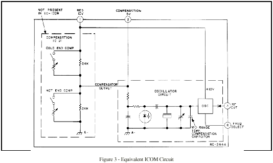
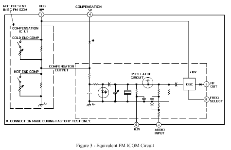
Both the 5C-ICOMs and 2C-ICOMs are temperature compensated at both ends of the temperature range to provide instant frequency compensation. An equivalent ICOM circuit is shown in Figure 3.
The cold end compensation circuit does not operate at temperatures above 0° C. When the temperature drops below 0° C, the circuit is activated. As the temperature decreases, the equivalent resistance decreases and the compensation voltage increases.
The increase in compensation voltage decreases the capacity of the varactor in the oscillator, increasing the output frequency of the ICOM.
The hot end compensation circuit does not operate at temperatures below +55° C. When the temperature rises above +55° C, the circuit is activated, As the temperature increases, the equivalent resistance decreases and the compensation volt-age decreases. The decrease in compensation voltage increases the capacity of the varactor, decreasing the output frequency of the ICOM.
In the 800 MHz version, the hot end compensation circuit consists of two branches; the first branch is activated at +55°C and the second branch is activated at +70°C so that both branches are now operating. At temperatures above these activation points, the equivalent resistance decreases thereby decreasing the compensation voltage. This increases the capacitance of the varicap thus reducing the output frequency of the ICOM.
SERVICE NOTE: Proper ICOM operation is dependent on the closely-controlled input voltages from the 10-Volt regulator. Should all of the ICOMs shift off frequency, check the 10-Volt regulator module.
FM ICOMS
as used in the Mastr II VHF PLL Exciter
The phase detector compares the 3rd harmonic of the FM-ICOM with the output frequency of the VCO (divided by 4) to derive an error voltage proportional to the frequency and phase difference of the two inputs. The error voltage is amplified, passed through a lead/lag filter and applied to a varactor which instantaneously corrects the output frequency and phase of the VCO to the 12th multiple of the FM ICOM frequency.
After the VCO frequency is locked, (a maximum of 20 milliseconds), the RF amplifiers are turned on and the RF carrier output is presented to the PA.
Temperature compensation is provided in the audio and voltage regulator circuits to assure frequency stability and distortion free communications over the specified operating temperature range.
Audio, supply voltages and control functions are connected from the system board to the exciter board through P902.
The PLL exciter contains up to eight FM ICOM’s, an Audio Processor and amplifier, bandpass filter, harmonic amplifier, phase lock loop, RF amplifiers, frequency lock detector, voltage regulators and temperature compensation circuits.
FM ICOMS (Frequency Modulated)
Three different types of FM ICOM’s are available for use in the exciter. Each ICOM contains a crystal-controlled Colpitts oscillator, and two of the ICOM’s contain compensator IC’s.
The different FM ICOM’s are:
5C-FM ICOM - contains an oscillator and a 5 part-per-million (±0.0005%) compensator IC. Provides compensation for EC-ICOM’s.
EC-FM ICOM - contains an oscillator only. Requires external compensation from a 5C-ICOM.
2C-FM ICOM - contains an oscillator and a 2 PPM (±0.002%) compensator IC. Will not provide compensation for an EC-FM ICOM.
The ICOM’s are enclosed in an RF shielded can with the type ICOM (5C-FM ICOM, EC-FM ICOM or 2C-FM ICOM) printed on the top of the can. Access to the oscillator trimmer is obtained through a hole in the top of the can.
Frequency selection is accomplished by switching the ICOM keying lead (terminal 9) to A- by means of the frequency selector switch on the control unit. In single-frequency radios, a jumper from H9 to H10 in the control unit connects terminal 9 of the FM ICOM to A-. The oscillator is turned on by applying a keyed +10 Volts to the external oscillator collector load resistor, R153, which forward biases an internal diode switch.
The FM ICOM’s have an audio input which receives audio from the audio processor circuit. Therefore, with Modulation present, the output frequency of the "FM" ICOM varies at an audio rate.
In standard 5 PPM radios using EC-FM ICOM’s, at least one 5C-FM ICOM or 5C ICOM must be used. The 5C ICOM is normally used in the receiver F1 position, but can be used in any receive position. A 5C-FM ICOM can be used in any transmit position.
Note - The EC and 5C type ICOM’s are not interchangeable with EC-FM or 5C FM type ICOM’s. The EC and 5C type ICOM’s are used only in the receivers. While the EC-FM and 5C-FM type ICOM’s are always used in the transmitter.
One 5C ICOM or 5C-FM ICOM can provide compensation for up to 15 EC ICOM’s or EC-FM ICOM’s in the transmitter and receiver. Should the 5C ICOM or the 5C-FM ICOM compensator fail in the open mode, the EC-FM ICOM’s will still maintain 2 PPM frequency stability from 0° to 55°C (+32°F to 131°F) due to the regulated compensation voltage (5 Volts) from the 10 Volt regulator IC. If desired, up to 8 5C-FM ICOM’s may be used in the radio.
The 2C-FM ICOM’s are self-compensated at 2 PPM and will not provide compensation for EC-FM ICOM’s.
Oscillator Circuit
Quartz crystals used in ICOM’s exhibit the traditional "S" curve characteristics of output frequency versus operating temperature.
At both the coldest and hottest temperatures, the frequency increases with increasing temperature. In the middletemperature range (approximately 0°C to 55°C), frequency decreases with increasing temperature.
Since the rate of change is nearly linear over the mid-temperature range, the output frequency change can be compensated by choosing a parallel compensation capacitor with a temperature coefficient approximately equal to and opposite that of the crystal.
Figure 2 shows the typical performance of an uncompensated crystal as well as the typical performance of a crystal which has been matched with a properly chosen compensation capacitor.
At temperatures above and below the mid-range, additional compensation must be introduced. An externally generated compensation voltage is applied to a varactor (voltage-variable capacitor) connected in parallel with the crystal.
Refer to Figure 3 for a simplified diagram of the FM ICOM.
A constant bias of 5 Volts (provided from Regulator IC U901 connected in parallel with the compensator) maintains varactor capacity at a constant value over the entire mid-temperature range. This compensation voltage achieves the ±2 PPM stability.
Modulation is accomplished with a hyperabrupt varicap connected in series with the crystal feedback capacitors. The varicap impedance is the dominant impedance in the loop. This allows large swings of load capacity with modulation, therefore, large frequency shifts are achieved for the modulated input. Biasing for the modulation varicap is provided by a voltage divider, R152 and R163, connected across the 10 volt regulator input at P902-7. A bias voltage of 6.2 volts is applied to pin 6 of all ICOM’s.
Compensator Circuits
Both the 5C ICOM’s and 2C-FM ICOM’s are temperature compensated at both ends of the temperature range to provide instant frequency compensation.
The cold end compensation circuit does not operate at temperatures above 0°C. When the temperature drops below 0°C, the circuit is activated. As the temperature decreases, the equivalent resistance decreases and the compensation voltage increases.
An increase in compensation voltage decreases the capacitance of the varactor in the oscillator, thereby increasing the output frequency of the ICOM.
The hot end compensation circuit does not operate at temperatures below +55°C. When the temperature rises above +55°C, the circuit is activated. As the temperature increases, the equivalent resistance decreases and the compensation voltage decreases. The decrease in compensation voltage increases the capacity of the varactor, decreasing the output frequency of the ICOM.
[ Home ] [GE Tech ]
please send additions or corrections to getech@hallelectronics.com
Hall Electronics, Inc.
815 E. Hudson St.
Columbus, Ohio 43211
USA
(614) 261-8871
Last updated 2/28/2004